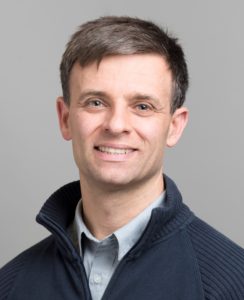
Tony Chan Carusone received his Ph.D. from the University of Toronto in 2002 and has since been a professor with the Department of Electrical and Computer Engineering at the University of Toronto. He is also an occasional consultant to industry in the areas of integrated circuit design and digital communication.
He and his graduate students have received seven best-paper awards at leading conferences for their work on chip-to-chip and optical communication circuits, analog-to-digital conversion, and precise clock generation. He was Editor-in-Chief of the IEEE Transactions on Circuits and Systems II: Express Briefs in 2009, an Associate Editor for the IEEE Journal of Solid-State Circuits 2010-2017, and is now Editor-in-Chief of the IEEE Solid-State Circuits Letters. He was a Distinguished Lecturer for the IEEE Solid-State Circuits Society 2015-2017 and currently serves on the Technical Program Committee of the International Solid-State Circuits Conference.
Find out more about Tony and his research at the Integrated Systems Laboratory at the University of Toronto.
Hi prof!
Could please do more videos on Sedra Microelectronics? If you can cover 10 chapters it would be really helpful to ace the course! Thanks 🙂
Hi Professor Tony
regarding the Analog IC Design textbook
do you provide any online course which covers the entire topics
of the textbook on any platform whether it is a free or paid course
thanks in advance
Besides the model files for MOSFET, is there any model file for BJT and diode? Thanks.
Here is a typical model for an NPN transistor:
.model QECL NPN(Is=0.26fA Bf=100 Br=1 Tf=0.1ns Cje=1pF Cjc=1.5pF Va=100)
And here are models of a typical discrete NPN, PNP and diode:
.model Q2N3904 NPN(Is=6.734f Xti=3 Eg=1.11 Vaf=74.03 Bf=416.4 Ne=1.259
+ Ise=6.734f Ikf=66.78m Xtb=1.5 Br=.7371 Nc=2 Isc=0 Ikr=0 Rc=1
+ Cjc=3.638p Mjc=.3085 Vjc=.75 Fc=.5 Cje=4.493p Mje=.2593 Vje=.75
+ Tr=239.5n Tf=301.2p Itf=.4 Vtf=4 Xtf=2 Rb=10)
.model Q2N3906 PNP(Is=1.41f Xti=3 Eg=1.11 Vaf=18.7 Bf=180.7 Ne=1.5 Ise=0
+ Ikf=80m Xtb=1.5 Br=4.977 Nc=2 Isc=0 Ikr=0 Rc=2.5 Cjc=9.728p
+ Mjc=.5776 Vjc=.75 Fc=.5 Cje=8.063p Mje=.3677 Vje=.75 Tr=33.42n
+ Tf=179.3p Itf=.4 Vtf=4 Xtf=6 Rb=10)
.model D1N4148 D(Is=2.682n N=1.836 Rs=.5664 Ikf=44.17m Xti=3 Eg=1.11 Cjo=4p
+ M=.3333 Vj=.5 Fc=.5 Isr=1.565n Nr=2 Bv=100 Ibv=100u Tt=11.54n)
Hi,
My professor is using one of the file here for an LTSpice assignment that is worth 40% of my final mark.
I need help adding 0.35 um CMOS file to LTSpice to use and simulate with. Any advice how to import?
I have tried adding to the directory but I have an error. I also tried the spice directive .op, but I don’t understand why there are three files _ss, _ff and _tt …etc.
Use the “.include” directive, pointing to the model file(s). Good luck!
Hello
How can I access to solutions manual?
thanks.
The solution manual is for active instructors only. Thanks for your interest.
Hi,
In chapter 6 (Basic Op-Amp Design and Compensation) on Page no. 252, you say slew-rate(SR) can be increased by increasing Veff.
But increasing Veff by some ratio, also decreases unity gain frequency(Wta) by same ratio, making SR independent of Veff.
Since SR = Veff*Wta.
Can you clarify, Please.
The key point is the assumption that the two-stage opamp is “properly compensated” as it says near the bottom of page 252. As you say, increasing Veff with constant bias current reduces the unity-gain frequency. Therefore, the compensation capacitor size can also be reduced while maintaining the same phase margin. This reduction in Cc provides an attendant improvement in slew rate.
Hi,Professors. Recently I am read the great book ” Analog integrated circuit design 2nd”, but I have a question about the sentence below( in page 180 of chapter4)
“This assumes rin<= or >>Rs, could you help me please.
Assuming rin << Rs means that Rs may be neglected in (4.162> and the time constant is approximately rinCgs. Then, a further assumption is made that rin is approximately 1/gm to arrive at the final expression in (4.162).