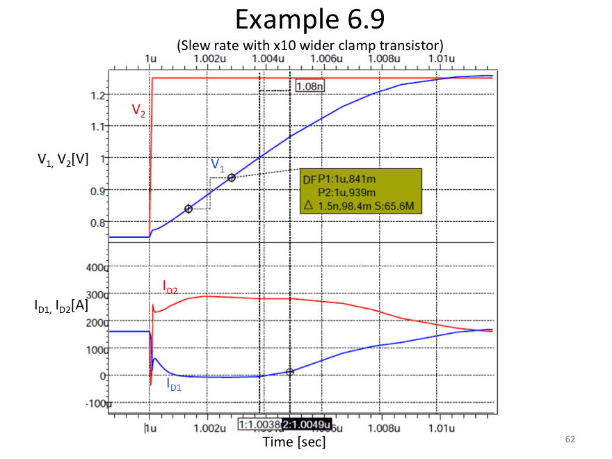
Example 6.9
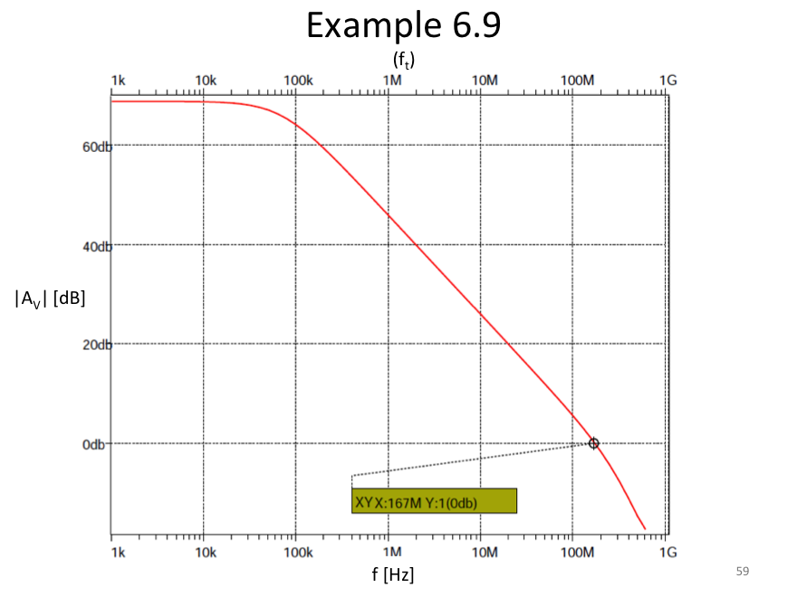
1. Unity-gain frequency
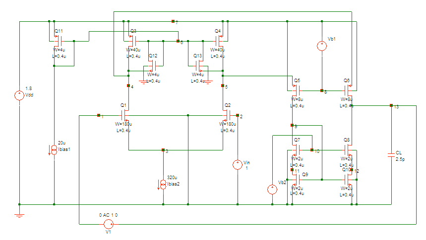
1-1. Schematic
1-2. HSPICE Netlist
* Example 6.9 for GBW
* MOS model
.include p18_cmos_models_tt.inc
* main circuit (Folded-cascode opamp)
m1 4 1 3 0 nmos L=0.4u W=180u
m2 5 2 3 0 nmos L=0.4u W=180u
m3 4 6 7 7 pmos L=0.4u W=40u
m4 5 6 7 7 pmos L=0.4u W=40u
m5 9 8 5 7 pmos L=0.4u W=8u
m6 13 8 4 7 pmos L=0.4u W=8u
m7 9 10 11 0 nmos L=0.4u W=2u
m8 13 10 12 0 nmos L=0.4u W=2u
m9 11 9 0 0 nmos L=0.4u W=2u
m10 12 9 0 0 nmos L=0.4u W=2u
m11 6 6 7 7 pmos L=0.4u W=4u
m12 6 6 4 0 nmos L=0.4u W=4u
m13 6 6 5 0 nmos L=0.4u W=4u
CL 13 0 2.5p
* current source
Ibias1 6 0 20u
Ibias2 3 0 320u
* voltage source
Vdd 7 0 1.8
Vb1 7 8 1.2
Vb2 10 0 1.2
Vin 2 0 1
V1 13 1 dc=0 ac=1
* analysis
.op
.ac dec 10 1k 1G
* options
.options post
.end
1-3. Simulation Result
2. SR without clamp transistors
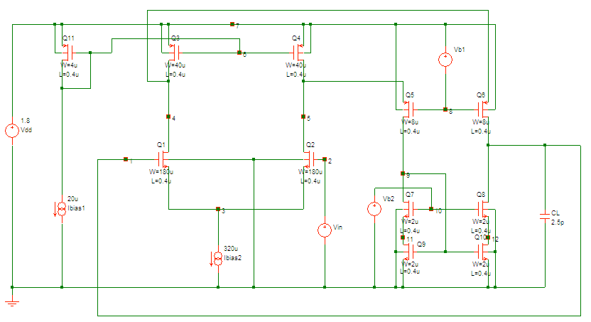
2-1. Schematic
2-2. HSPICE Netlist
* Example 6.9 for SR without clamp transistors
* MOS model
.include p18_cmos_models_tt.inc
* main circuit (Folded-cascode opamp)
m1 4 1 3 0 nmos L=0.4u W=180u
m2 5 2 3 0 nmos L=0.4u W=180u
m3 4 6 7 7 pmos L=0.4u W=40u
m4 5 6 7 7 pmos L=0.4u W=40u
m5 9 8 5 7 pmos L=0.4u W=8u
m6 1 8 4 7 pmos L=0.4u W=8u
m7 9 10 11 0 nmos L=0.4u W=2u
m8 1 10 12 0 nmos L=0.4u W=2u
m9 11 9 0 0 nmos L=0.4u W=2u
m10 12 9 0 0 nmos L=0.4u W=2u
m11 6 6 7 7 pmos L=0.4u W=4u
CL 1 0 2.5p
* current source
Ibias1 6 0 20u
Ibias2 3 0 320u
* voltage source
Vdd 7 0 1.8
Vb1 7 8 1.2
Vb2 10 0 1.2
Vin 2 0 1 pulse(0.75 1.25 0 0.1n 0.1n 499.8n 1u)
* analysis
.op
.tran 0.01n 2u
* options
.options post
.end
2-3. Simulation Result
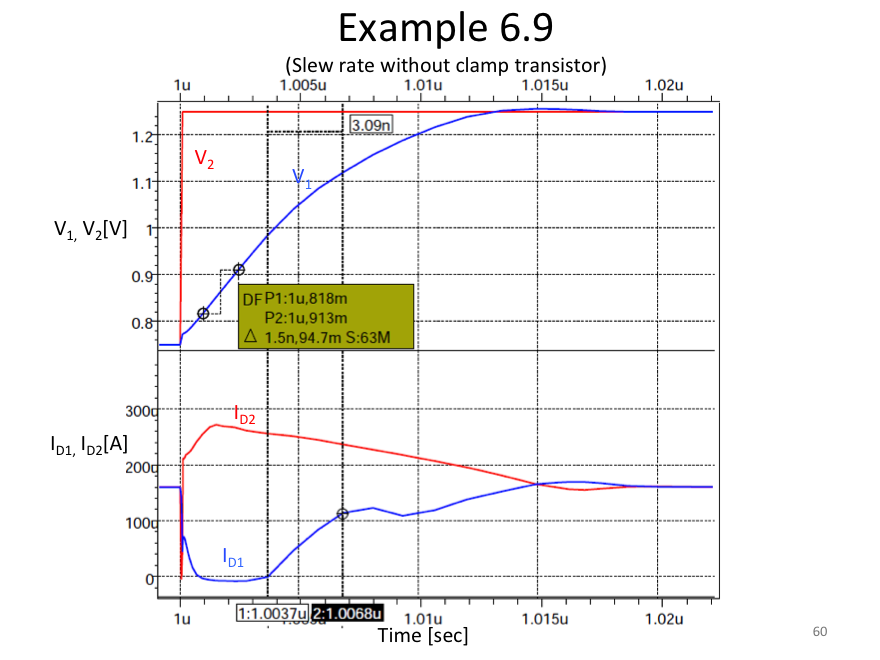
Slew-rate = 63V/µs
Recovery time from slew-rate limiting = 3.1nsec
3. SR with clamp transistors
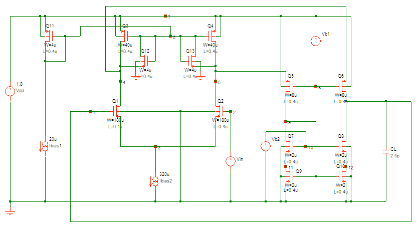
3-1. Schematic
3-2. HSPICE Netlist
* Example 6.9 for SR with clamp transistors
* MOS model
.include p18_cmos_models_tt.inc
* main circuit (Folded-cascode opamp)
m1 4 1 3 0 nmos L=0.4u W=180u
m2 5 2 3 0 nmos L=0.4u W=180u
m3 4 6 7 7 pmos L=0.4u W=40u
m4 5 6 7 7 pmos L=0.4u W=40u
m5 9 8 5 7 pmos L=0.4u W=8u
m6 1 8 4 7 pmos L=0.4u W=8u
m7 9 10 11 0 nmos L=0.4u W=2u
m8 1 10 12 0 nmos L=0.4u W=2u
m9 11 9 0 0 nmos L=0.4u W=2u
m10 12 9 0 0 nmos L=0.4u W=2u
m11 6 6 7 7 pmos L=0.4u W=4u
m12 6 6 4 0 nmos L=0.4u W=4u
m13 6 6 5 0 nmos L=0.4u W=4u
CL 1 0 2.5p
* current source
Ibias1 6 0 20u
Ibias2 3 0 320u
* voltage source
Vdd 7 0 1.8
Vb1 7 8 1.2
Vb2 10 0 800m
Vin 2 0 1 Pulse(0.75 1.25 0 0.1n 0.1n 499.8n 1u)
* analysis
.op
.tran 0.1n 3u
* options
.options post
.end
3-3. Simulation Result
Slew-rate = 63V/µs
Recovery time from slew-rate limiting = 2.7nsec
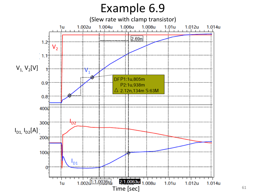
*The clamp transistor does not work well when they are sized as in the textbook because the supply voltage is too low to support Vgs across Q11 and Q12/13 in series so the input transistors enter the triode region. If ten-times larger MOSFETs (W=40µm) are used for the clamps as shown in the figure below, their Vgs is made small enough to keep the transistors in active mode.”
