Example 6.1
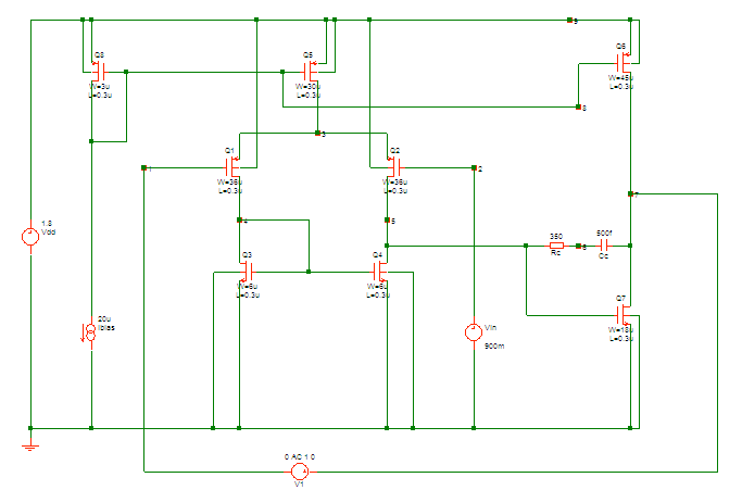
1. Schematic
2. HSPICE Netlist
* Example 6.1
* MOS model
.include p18_cmos_models_tt.inc
* main circuit (Two-stage amplifier)
* input pair
m1 4 1 3 9 pmos w=36u l=0.3u
m2 5 2 3 9 pmos w=36u l=0.3u
* active load for diff pair
m3 4 4 0 0 nmos w=6u l=0.3u
m4 5 4 0 0 nmos w=6u l=0.3u
* tail current
m5 3 8 9 9 pmos w=30u l=0.3u
* output stage
m6 7 8 9 9 pmos w=45u l=0.3u
m7 7 5 0 0 nmos w=18u l=0.3u
* biasing
m8 8 8 9 9 pmos w=3u l=0.3u
rc 5 6 350
cc 6 7 1p
* current source
Ibias 8 0 20u
* voltage source
Vdd 9 0 1.8
Vin 2 0 0.9
V1 7 1 dc=0 ac=1
* analysis
.op
.ac dec 10 1k 100G
* options
.options post
.end


I have a question, why the gate of Q1 is connected to node7 through a ac voltage source?
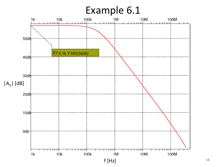
Is it a feedback? And how the fianl Av means?
Does it mean V(node7)/Vin?
THX
Good question. This simulation is using a little-known method for injecting a test voltage signal into a feedback loop. A test voltage signal can be introduced in series at an appropriately-chose node within the loop. The advantage of this method is that it does not disturb the dc operating point of the circuit, which for high-gain feedback loops like this one is a very sensitive parameter. For this method to work, the node must be chosen so that the impedance looking forward around the loop is much higher than the impedance looking backward around the loop. This is clearly the case for the circuit in this example, and the
gain, |Av|, is given by |V(7)/V(in)| = |V(7)/V(1)|. Details of this method may be found in the classic 1975 paper, “Measurement of loop gain in feedback systems” by R.D. Middlebrook.